

 +86 19108238286
A coupling is a mechanical device that is used to transfer power from one rotating shaft to another by joining two of them at their ends. In order to guarantee the transfer of torque and rotational movement between linked components and enable the transfer of power in a variety of industrial and mechanical applications, couplings are crucial components of machinery.


Key Functions of Couplings:
Power Transmission: To transfer torque and rotational motion from a driving shaft, such as a motor, to a driven shaft, such as a pump, gearbox, or generator, couplings are used to join two shafts.
Misalignment Accommodation: Small misalignments between coupled shafts can be accommodated using couplings. There are several kinds of misalignments, such as:
- Axial Misalignment: When there is a difference in the axial position of the shafts.
2. Angular Misalignment: When the shafts are at an angle to each other.
3. Parallel Misalignment: When the shafts are parallel but not collinear.
Absorption of Shock Loads: The ability of couplings to withstand shock loads and vibrations helps shield linked machinery from harm from abrupt changes in operation or torque spikes.
Adjustment for Thermal Expansion: Certain couplings have the capacity to adjust for variations in shaft position brought on by thermal expansion, guaranteeing steady functioning even when the machinery they are connected to warms up while in use.
Connection Flexibility: In many applications, couplings give the system flexibility by making it simple to disconnect and reattach equipment, which makes maintenance and repair activities easier.
Types of Couplings:
Here are some common types of couplings used in machinery, each designed to handle specific needs and conditions:
1. Rigid Couplings:
Since they prevent any misalignment between linked shafts, rigid couplings are utilised when exact shaft alignment is necessary. When shafts are completely aligned and high torque gearbox without flexibility is required, these couplings are perfect.
- Flange Couplings: These have two flanged hubs bolted together. They are used in applications where alignment is fixed and precise.
- Sleeve or Muff Couplings: Simple cylindrical sleeves that connect two shafts, used for straightforward, rigid connections.
2. Flexible Couplings:
Flexible couplings lower the chance of machinery damage by absorbing shocks and vibrations and accommodating a certain amount of misalignment.
- Elastomeric Couplings: These are designed to accept small misalignments and absorb shocks by using a flexible material (usually plastic or rubber). Tire couplings and jaw couplings are two examples.
- Gear Couplings: These couplings transmit high torque while allowing for angular and parallel misalignment thanks to internal and exterior gears. Usually, heavy-duty settings like steel mills or cranes employ them.
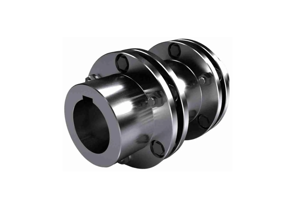
- Disc Couplings: These use metal discs that are flexible enough to flex to account for misalignment without sacrificing the solid, rigid connection needed to transfer torque. They are renowned for their dependability and longevity and are appropriate for high-speed, high-torque applications.
- Grid Couplings: They are made out of a grid that slides into slots on two hubs to provide flexibility and the capacity to withstand vibrations and shock loads. They are frequently employed in demanding situations where shock absorption is essential.
- Chain Couplings: These couplings are perfect for low-speed, high-torque applications because they can tolerate minor misalignment, much like a roller chain and sprockets.
3. Fluid Couplings:
Fluid couplings use a hydraulic fluid to transfer torque between shafts. They provide a smooth and controlled beginning, which is particularly useful when a gradual acceleration is required to prevent shock loading.
Hydrodynamic Couplings: Controlled acceleration and deceleration are made possible by applying the laws of hydrodynamics. They are frequently utilised in blowers, fans, and conveyor systems where silent operation is essential.
4. Magnetic Couplings:
Magnetic couplings are perfect for enclosed settings where contamination or leakage must be avoided because they employ magnetic fields instead of a direct mechanical connection to transfer torque between shafts.
Permanent Magnetic Couplings: These are utilised in applications, such pumps for corrosive or hazardous fluids, where total isolation between the motor and the driven load is necessary.
5. Universal Joints (U-Joints):
Universal joints are appropriate for situations where shafts must be connected at angles or where movement is required because they permit a large degree of angular misalignment between linked shafts.
Cardan Shaft (Double U-Joint): This type of joint allows for angular misalignment and compensates for axial movement. It is made up of two U-joints joined by a shaft.
6. Oldham Couplings:
Three components make up an Oldham coupling: a floating disc connecting the two hubs. They can be used in low to moderate torque situations because they permit a little degree of axial movement and parallel misalignment.
7. Bellows Couplings:
The bellows nature of these couplings allows them to flex while still delivering torque. They are perfect for applications like precision positioning systems that call for zero backlash and strong torsional stiffness.
8. Diaphragm Couplings:
Diaphragm couplings transfer torque while allowing for axial and angular misalignment thanks to a flexible diaphragm. Low inertia and great dependability are essential in high-speed applications where they find employment.
9. Torsional Couplings:
These couplings are frequently employed in applications with cyclic loads, such as internal combustion engines and compressors. They are made to absorb and attenuate torsional vibrations.
Selecting the appropriate coupling type is contingent upon various aspects, including the necessary torque transfer, shaft alignment, elasticity, shock absorption, and application-specific requirements. The longevity of machinery is increased, wear and tear is decreased, and efficient operation is ensured by careful selection.
Purpose of using couplings?
In mechanical systems, couplings are primarily used to join two spinning shafts and facilitate the effective transfer of power between them. Couplings, however, perform a number of additional crucial tasks that improve the efficiency and dependability of machinery. Here’s a thorough examination of the main goals of coupling use:
1. Power Transmission
When two shafts are connected by couplings, torque and rotational motion can be transferred from a driving shaft—like a motor—to a driven shaft—like a gearbox, conveyor, or pump. This makes it possible for the machinery to efficiently carry out its intended job.
2. Compensation for Misalignment
By accommodating different kinds of misalignments between connected shafts, couplings can shield equipment from undue wear and damage. Misalignment comes in various forms.
- Angular Misalignment: When the shafts are at an angle to each other.
- Parallel Misalignment: When the shafts are parallel but not collinear.
- Axial Misalignment: When there is a difference in the axial position of the shafts.
By compensating for these misalignments, couplings help maintain the alignment of machinery components and ensure smooth operation.
3. Absorption of Shock Loads and Vibrations
The purpose of couplings is to mitigate shock loads and reduce vibrations resulting from abrupt shifts in torque, operational modifications, or misalignment. This protective feature lessens wear and strain on the machinery’s components, extending its operational life and preventing damage.
4. Allowance for Thermal Expansion and Contraction
Temperature variations can cause equipment to expand or contract in a variety of applications. These variations in shaft position can be accommodated via couplings, guaranteeing consistent alignment and seamless functioning even as the machinery heats up or cools down while in use.
5. Flexibility and Easy Maintenance
Couplings give mechanical systems flexibility by making it simple to disconnect and reattach machine parts. This saves time and minimises downtime by making it simpler to carry out maintenance, repairs, or replacements without having to disassemble complete equipment pieces.
6. Protection Against Overloads
Certain couplings are made with safety features in mind, guarding against overloads on machinery. For instance, some coupling types include the ability to slip or disengage in the event of a torque overload, protecting the motor, shafts, and other associated parts from harm.
7. Transmission of Motion in Sealed or Isolated Environments
Applications where a physical connection between shafts must be avoided, including handling hazardous goods or sealed settings where contamination must be avoided, call for the usage of magnetic couplings. Without physical touch, the torque is transmitted by the magnetic field, guaranteeing a clean and safe operation.
8. Minimization of Backlash
Couplings are employed in precision applications, including robots and CNC machinery, to reduce backlash, which is the little movement that happens between gears or related components when motion is reversed. This guarantees extremely accurate and precise movement and positioning.
9. Accommodation of Shaft End Float and Angular Deflection
Certain couplings permit restricted angular deflection and axial movement (shaft end float), allowing for movement in the attached equipment and lowering bearing and other component stress.
10. Ensuring Operational Safety
Couplings are vital components that keep mechanical systems safe, avert accidents, and safeguard people and equipment by absorbing shocks, allowing for misalignment, and enabling safe separation during repair.
Parameter for choosing couplings:
For machinery to operate dependably and effectively, the proper coupling selection for a given application is essential. The decision is based on a number of variables, all of which need to be carefully taken into account in order to match the coupling’s features to the requirements of the application. These are the main factors to take into account while selecting a coupling:
1. Torque Requirements
- Nominal Torque: Without sliding or failing, the coupling must be able to withstand the torque generated by the driving apparatus. This entails being aware of the system’s potential peak and sustained torque values.
- Peak or Maximum Torque: Consider any possible overload situations, such as startup or shutdown scenarios, in addition to the nominal torque, and make sure the coupling can withstand these peaks without suffering damage.
2. Shaft Size and Connection Type
- Shaft Diameters: The diameter of the connection and the shafts it is joining must match. The majority of couplings are made to accommodate particular shaft diameters.
- Keyways and Splines: In order to ensure correct engagement and torque transfer, the coupling must be compatible with keyways or splines on the shafts.
3. Type of Misalignment
- Angular Misalignment: The angle between the axes of the connected shafts. Some couplings can tolerate more angular misalignment than others.
- Parallel Misalignment: The lateral offset between the shafts. Ensure the coupling can accommodate the degree of parallel misalignment present in the setup.
- Axial Misalignment: The amount of axial movement or separation between the shafts. Some couplings are designed to handle axial misalignment more effectively than others.
4. Speed of Operation
- Rotational Speed (RPM): The choice of connection is affected by the machinery’s working speed. Couplings for high-speed applications need to be dynamically balanced and able to function without vibrating or becoming unstable.
5. Environmental Conditions
- Temperature Range: The coupling material and design must withstand the operating temperature range of the environment.
- Corrosive or Humid Conditions: In harsh environments (e.g., chemical plants, outdoors), choose couplings made from materials resistant to corrosion and wear.
- Exposure to Chemicals: If the coupling will be exposed to chemicals, ensure it is made from materials that can resist chemical attack.
6. Vibration and Shock Absorption
- Shock Loads: Choose a connection that can absorb unexpected torque spikes or shocks without damaging linked components by transferring no vibrations at all.
- Vibration Damping: Select a coupling with good damping capabilities for applications like precision machinery where there should be less vibration transmission.
7. Flexibility and Rigidity Requirements
- Flexibility: Some applications require couplings that can accommodate more flexibility due to frequent misalignment or movement (e.g., flexible couplings like elastomeric or disc couplings).
- Rigidity: Rigid couplings provide a more solid connection with no allowance for misalignment and are suited for applications requiring precise alignment.
8. Space Constraints
- Physical Size: The coupling needs to fit inside the machinery’s accessible space. To guarantee correct installation and operation, take into account the total dimensions, including length and diameter.
- Accessibility for Maintenance: Make sure there is adequate room surrounding the coupling for routine upkeep, examination, and possible replacement.
9. Maintenance and Serviceability
- Ease of Installation and Maintenance: Certain couplings require less maintenance and are simpler to install than others. Select a connection based on the maintenance requirements and capabilities of your business.
- Wear Parts and Replacement: Compared to other couplings, some are less maintenance-intensive and easier to install. Select a coupling based on your operation’s maintenance requirements and capabilities.
10. Cost and Availability
- Initial Cost vs. Long-term Reliability: Compare the coupling’s initial cost with its anticipated lifespan, maintenance requirements, and dependability. A more costly coupling might, in some circumstances, provide superior value because of its longer lifespan and less maintenance.
- Availability of Spares: Make sure spare couplings or replacement components are easily accessible, particularly for vital applications where downtime is expensive.
11. Type of Load
- Constant or Variable Load: Determine if there will be a constant or varying load on the coupler. Couplings made to withstand these circumstances are needed for applications with frequent start-stop cycles or varying loads.
12. Safety Requirements
- Safety Features: When safety is a top priority, look for couplings with features like overload prevention (shear pin couplings, for example) that stop damage or accidents in the event of a mechanical failure.
Common Coupling issue and how to prevent them:
In rotating equipment, couplings are crucial parts that join two shafts and transfer power while allowing for some misalignment. Coupling failures, however, can result from a variety of misalignment kinds, each with its own set of symptoms and reasons. We’ll look at the most typical coupling problems in this post and provide helpful solutions.
Issue 1 : Angular Misalignment
What is it?
When the coupling’s connecting shafts are not properly aligned, it creates an angular misalignment, which causes the coupling to flex unevenly.
Signs to Watch Out for:
High axial vibration: Usually observed at shaft speeds of 1x, 2x, and 3x; the vibration at 2x is frequently more noticeable than at 1x.
Phase variations: The vibration phase may exhibit a continuous relationship of roughly 180° across the connection.
Growing radial vibration over time: This is because the disc pack is “unravelling” little by bit.
Damage that is visible: You may see traces of fretting, a type of wear brought on by frequent contact, at the fracture places, or you may observe cracks close to the bolt holes.
Common Reasons:
Thermal movement or expansion,
settling of the foundation improperly,
orientation is impacted by pipe strain,
loose studs or anchor bolts,
During installation, there was poor initial alignment.
How to Correct It:
Verify alignment: Observe the face runout and parallel offset on both coupling sides, as angular misalignment may result in disparities between the ends.
Take thermal growth into consideration: Conduct a hot alignment to account for equipment expansion if thermal movement is an issue.
Issue 2 : Misalignment of the axes
What is it?
When there is a difference in the axial distance between the pieces of equipment linked by the connection, axial misalignment takes place. This misalignment may put the connection and any attached gear under more strain.
Signs to Watch Out for:
Elevated axial vibration: Frequently correlated with variations in motor current, particularly when the motor rotor is not aligned with its magnetic centre.
Increased thrust bearing temperatures: One of the most important signs of axial misalignment is this.
Axial measurements that pulse: This is the result of the machine pushing in an attempt to correct the misalignment.
Common Reasons:
Inaccurate thermal growth calculations,
Displacement of equipment from its magnetic centre,
incorrect starting alignment.
How to Correct It:
Verify the alignment and axial spacing: Make sure the motor rotor is on its magnetic centre and that the coupling’s axial capacity meets the equipment’s end play.
Examine the values for thermal growth: Based on precise measurements of thermal growth, adjust the alignment of the equipment.
Issue 3 : Torque Overload
What is it?
When the torque supplied via the connection surpasses its intended capacity—often as a result of unforeseen or abnormal events—torque overload occurs.
Signs to Watch Out for:
Unexpected failure: Failures due to torque overload can occur suddenly and are difficult to forecast.
Noise and imbalance: When a disc pack yields, you might hear strange noises. You might also notice an imbalance since the disc packs are buckled.
Physical damage: The disc packs may exhibit obvious spreading or buckling, and the disc pack bolts may come into contact with the clearance holes.
Common Reasons:
Electrical malfunctions,
Slug of liquid in compressors,
high torque at starting,
Unexpected incidents during operations.
How to Correct It:
Examine any damage: Check for cracks right away, and repair coupling parts as necessary.
Evaluate the coupling size: To avoid overloads in the future, make sure the coupling is the right size and think about utilising a shear pin or shear spacer design.
Examine the history of operations: Examine any odd occurrences that might have contributed to the overload.
Issue 3 : Torsional Oscillation
What is it?
Torsional oscillation, which may result in coupling failure, is the twisting motion of the shafts caused by resonance or external excitation.
Signs to Watch Out for:
Hard to find without precise measurements: Torsional oscillations are generally imperceptible and difficult to spot without torque monitoring.
Correlation with radial vibration: Torsional vibrations in systems with geared trains may coincide with specific frequencies of radial vibrations.
Physical damage: There may be fretting at the clamping area and link centres, as well as fractures in the disc links’ centres.
Common Reasons:
Drives with Variable Frequency (VFD) Excitation,
torsional resonance frequencies,
“Whipping action” brought on by motor slide at startup.
How to Correct It:
Examine and modify the coupling’s stiffness and inertia: To reduce torsional problems as you analyse the torsional behaviour of the system.
Keep an eye on torque: To identify oscillations early, use a torque monitoring device.
Verify the VFD settings: Make sure the VFD drive parameters are adjusted appropriately to reduce the frequency of excitation.
Conclusion:
Choosing the right coupling means carefully considering the needs of your specific application to ensure the machinery runs smoothly and reliably. By selecting the appropriate coupling, you can reduce wear and tear on your equipment, lower maintenance costs, and avoid unexpected breakdowns, keeping your operations efficient and trouble-free.
At Hengyo we use High-grade components like cast iron, steel, and aluminium to create our shaft couplings , guaranteeing their performance and longevity. Every connection is constructed in accordance with strict international standards, such as ANSI, DIN, UNI, and ISO. This implies that you can rely on them to consistently provide outstanding technical performance.
Our couplings are developed to minimise shock, vibration, misalignment, and overload while providing excellent torsional performance and easy handling of power transmission. Our couplings are a good option for guaranteeing smooth and effective functioning in your machinery because they are long-lasting and dependable, regardless of the light, medium, or heavy motor and internal combustion engine applications you operate with. Connect with us at arie@sc-hengyo.com or call +86 19108238286.